

Rotavator Vibrating or Noisy Mid-Field? Cross & Yoke Wear Signs
By MOD Plus | Agricultural Driveline & PTO Transmission Specialists, Sanjay Gandhi Transport Nagar, Delhi

A rotavator that runs silent and smooth one season can start shaking, knocking, or humming the next — often mid-field, often at the worst possible moment before sowing. Most operators respond to this the same way: they turn up the tractor's RPM to push through it, or they simply keep working and hope the sound goes away. Neither response addresses what is actually happening. Vibration and noise in a rotavator driveline are not cosmetic annoyances. They are the earliest, most honest diagnostic signals a PTO shaft can give — and by the time they are loud enough to notice from the tractor seat, wear has usually already been progressing for weeks.
This guide is built specifically to answer one question with precision: what is my rotavator's vibration or noise actually telling me, and what do I do about it? It is the diagnostic companion to MOD Plus's Rotavator Cross Complete Guide, which covers cross selection, sizing, and buying decisions in depth, and to the Rotavator Cross & Yoke PTO Parts Guide, which covers the full product range. Where those guides teach you what to buy, this guide teaches you how to listen to your machine, read its symptoms correctly, and know exactly which component — cross, yoke, tube, gearbox, or something further up the driveline — needs attention before a field breakdown forces the decision for you.
Every diagnostic pathway in this guide is built around components that actually exist in MOD Plus's Rotavator Parts range, covering Shaktiman, Sonalika, Mahindra Rotavator, Mahindra Gyrovator, Maschio, Howard, Fieldking, Commer, and Mini Rotavator configurations. Where a specific part number solves a specific diagnosed problem, it is named directly — because the fastest path from a diagnosed symptom to a fixed machine is a verified part number, not a guess.
Featured Snippet Answer — Why Is My Rotavator Vibrating or Noisy? Rotavator vibration and noise almost always originate in the PTO driveline's universal joint — specifically, wear in the UJ cross's needle bearings, elongation or bore wear in the yoke that holds it, or an operating angle beyond the joint's design limit. Less commonly, the cause lies in rotor blade imbalance, gearbox bearing wear, a worn slip clutch, or a bent driveshaft tube. The exact pattern of the vibration or noise — when it starts, how it changes with speed or turning, and whether it is constant or periodic — identifies which of these it is.
Table of Contents
Understanding Vibration and Noise: The Physics of a Rotavator Driveline
The PTO Driveline From End to End: A Quick Anatomy Refresher
The Master Diagnostic Table: Every Symptom, Cause, and Urgency Level
Why a Worn Cross Destroys a Yoke: The Mechanical Chain Reaction
Beyond the Cross: Other Sources of Rotavator Vibration and Noise
Understanding Vibration and Noise: The Physics of a Rotavator Driveline
Before a symptom can be diagnosed correctly, it helps to understand what vibration and noise actually are — because farmers, mechanics, and dealers frequently use the two words interchangeably when they describe genuinely different physical events with different root causes.
What Vibration Actually Is
Vibration is repetitive mechanical motion — a component moving back and forth, or rocking around a point, faster than the eye can follow. In a rotating driveline, vibration is almost always caused by one of three underlying conditions:
Dynamic imbalance. Every rotating part has a centre of mass. If that centre of mass does not sit exactly on the axis of rotation, the part generates a centrifugal force that pulls outward once per revolution. At low speed this force is small and unnoticeable. Because centrifugal force increases with the square of rotational speed, the same imbalance becomes dramatically more forceful as PTO speed rises from idle to full 540 or 1000 RPM operation. This is why a rotavator can feel acceptable at low tractor throttle and shake noticeably the moment the operator brings the PTO up to full working speed.
Misalignment. A driveline is designed to operate within a defined working angle — the angle between the tractor's PTO output shaft and the rotavator gearbox's input shaft. Within that design angle, the universal joint's cyclic speed variation (explained below) is accounted for in the component's engineering. Push the angle beyond the design limit — through incorrect hitch height, an implement mounted at the wrong depth, or a three-point linkage that is not level — and the joint is forced to articulate further than intended on every single revolution. This produces vibration that scales directly with how far out of alignment the driveline is running.
Mechanical looseness. Once a component wears — a bearing cup develops play, a yoke bore goes oversize, a spline loosens — the parts that were previously in tight, controlled contact are now free to move slightly relative to one another. That freedom of movement, multiplied by hundreds of revolutions per minute, becomes vibration. This is the category that covers the majority of cross and yoke wear symptoms described throughout this guide.
What Noise Actually Is
Noise is the audible byproduct of vibration and impact. When a worn or misaligned component moves suddenly against another surface — a needle roller striking a flat-worn section of bearing cup, a loose yoke fork knocking against its stop, a spline rattling in a worn bore — the impact generates a sound wave that travels through the metal structure and through the air to the operator's ear.
This is why vibration and noise so often appear together, and why noise typically appears after vibration in a component's wear timeline: vibration is the underlying motion; noise is the sound produced once that motion becomes forceful enough to generate audible impacts. A cross in the earliest stage of bearing wear may already be running slightly rough — undetectable without disassembly — for weeks before it produces enough looseness to generate an audible knock. By the time noise is present, mechanical wear has already reached a measurable stage.
How Vibration Travels Through a Driveline
Vibration does not stay where it starts. It travels along the driveshaft as a mechanical wave, transmits through the yoke splines into the tractor's PTO stub shaft and into the rotavator gearbox's input shaft, and from there into the tractor seat, the operator's hands on the controls, and the implement's mounting frame. This is precisely why a worn 38mm UJ cross — a component that weighs a few hundred grams — can make an entire multi-hundred-kilogram rotavator shudder, and why ignoring the vibration does not just risk the cross. It risks every bearing, spline, and seal that the vibration passes through on its way outward.
Rotational Force, Angular Velocity, and Why Universal Joints Vibrate by Design
There is one additional layer of physics specific to universal joints that is worth understanding, because it explains why even a perfectly healthy rotavator driveline is never perfectly smooth, and why the goal of good maintenance is to keep vibration within a normal, harmless range rather than eliminate it entirely.
A single universal joint — one cross, two yokes — does not transmit rotational speed uniformly when it is operating at an angle. As the input shaft rotates at a constant speed, the output shaft's instantaneous speed accelerates and decelerates twice per revolution. This is a basic property of the joint's geometry, not a defect. At small working angles (a few degrees) this cyclic speed variation is negligible. As the working angle increases, the variation becomes more pronounced, producing genuine torsional vibration even in a brand-new, correctly lubricated cross and yoke.
This is precisely why excessive operating angle appears repeatedly throughout this guide as a root cause. It is not simply "bad for the parts" in a vague sense — it is a direct, measurable amplifier of the cyclic vibration that the joint's own geometry produces, on top of whatever additional vibration component wear contributes.
The PTO Driveline From End to End: A Quick Anatomy Refresher
Every vibration or noise diagnosis in this guide refers back to specific points along the driveline. If you are already familiar with rotavator PTO shaft construction, skip ahead to the Master Diagnostic Table. If not, here is the complete path power takes from tractor to soil:
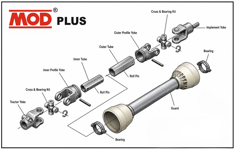
Tractor PTO stub shaft — the splined output shaft on the rear of the tractor, rotating at a standard 540 or 1000 RPM.
Spring yoke (input yoke) — locks onto the tractor PTO stub shaft using a spring-loaded collar. MOD Plus supplies this in multiple tooth counts and lock configurations across the Rotavator Parts range.
UJ cross (universal joint cross) — the cruciform component with four needle-bearing-supported trunnion journals, allowing the shaft to articulate through a working angle while transmitting full torque.
Telescoping triangular tube set — the sliding inner/outer tube section that allows the driveshaft to extend and retract as implement height changes during operation.
Second UJ cross and half yoke / triangle yoke — the joint at the implement end, connecting to the rotavator gearbox input shaft.
Shearing bolt yoke or safety coupling (where fitted) — a deliberate mechanical weak point that protects the entire driveline from torque spikes.
Rotavator gearbox — steps down and redirects rotational power from the driveshaft to the horizontal rotor shaft.
Rotor and blades — the rotating assembly that actually cultivates the soil, carrying the tillage blades in their holders.
Driveshaft guard/shield — the protective tube covering the entire external driveshaft assembly, a safety component rather than a mechanical one, but relevant to noise diagnosis if it rattles or contacts the shaft.
Vibration or noise can originate at any one of these nine points. The sections that follow teach you how to identify which one, using only what you can observe, hear, and feel from the operator's seat and with a basic hand inspection.
The Master Diagnostic Table: Every Symptom, Cause, and Urgency Level
Use this table as the first stop for any rotavator vibration or noise complaint. Find the row that matches what you are experiencing, then follow the link to the deeper diagnostic section for that symptom category.
Symptom | Likely Cause | Inspection Method | Urgency | Risk if Ignored | Typical Downtime if Addressed Now |
Light vibration only at full PTO speed | Early UJ cross bearing wear; minor rotor imbalance | Hand-rotate cross; check grease colour | Low–Medium | Progresses to noise and yoke wear within weeks | Under 1 hour |
Heavy vibration throughout operation | Advanced cross wear; bent driveshaft tube; badly worn yoke bore | Remove shaft; check for play and straightness | High | Risk of sudden trunnion fracture and shaft disengagement | 2–4 hours |
Periodic vibration (once or twice per revolution) | Excessive working angle; bent shaft; single-plane imbalance | Check hitch height and three-point alignment | Medium | Accelerates fatigue on every driveline component | Under 1 hour (angle correction) |
Constant vibration regardless of angle or speed | Rotor/blade imbalance; gearbox bearing wear | Inspect rotor for damaged/missing blades | Medium–High | Gearbox bearing failure; rotor shaft damage | Half day |
Noise while turning at headlands | Working angle exceeding design limit during turns | Observe angle during turn; check lift height | Medium | Concentrated wear at angle extremes on every pass | Adjustment only |
Noise under heavy soil load | Cross bearing wear surfacing under torque; shear bolt near limit | Listen under load vs idle PTO | High | Cross seizure or shear bolt failure mid-row | 1–3 hours |
Noise only at PTO engagement | Loose yoke spline; worn shear pin/bolt seating | Check spline fit and shear bolt condition | Medium | Spline wear accelerates; shear bolt may fail early | Under 1 hour |
Noise appearing only after warming up | Grease breakdown under heat; bearing cup starting to seize | Feel driveshaft temperature after use | High | Bearing collapse; cross seizure | 1–2 hours |
Noise during road transport (PTO disengaged) | Loose driveshaft guard; worn triangular tube; loose safety chain | Inspect guard fasteners and tube fit | Low–Medium | Guard failure; tube wear from unsupported rattling | Under 1 hour |
Noise only at high RPM | Dynamic imbalance amplified by rotational speed; loose bearing cup | Compare noise at 540 vs 1000 RPM settings | Medium | Imbalance forces increase with the square of speed | 1–2 hours |
Knocking that varies rhythmically with shaft rotation | Flat-spotted needle bearing or damaged trunnion journal | Rotate shaft slowly by hand, feel for each knock | High | Rapid bearing collapse | 1–2 hours |
Grinding or metallic screech | Bearing cup seizure; dry metal-to-metal contact | Stop immediately; check temperature and grease | Critical | Trunnion fracture; catastrophic driveline failure | Immediate — do not operate |
Sudden loud bang followed by loss of drive | Shear bolt failure (normal) or trunnion fracture (abnormal) | Inspect shear coupling first, then full driveline | Critical | If not a shear bolt: further undiagnosed damage | Varies — inspect before resuming |
Visible shaft whip or bowing during rotation | Bent driveshaft tube; extreme imbalance | Stop and visually inspect from a safe distance | Critical | Shaft failure; safety hazard to operator and bystanders | Do not operate until replaced |
Diagnosing by Vibration Pattern
Not all vibration means the same thing. The pattern — how strong it is, when it appears, and whether it repeats predictably — narrows the diagnosis significantly before you ever pick up a tool.
Light Vibration
Light vibration is a faint tremor felt through the tractor seat or the implement's top link, usually only noticeable once the operator has spent enough hours on the machine to have a feel for how it normally runs. This is the single most valuable symptom in this entire guide, because it is almost always the earliest detectable sign of a developing problem — and the cheapest one to fix.
Light vibration at this stage is most commonly caused by the first measurable wear inside a UJ cross's needle bearings. The rollers have not yet flattened enough to produce an audible knock, but enough microscopic wear has occurred that the cross no longer rotates with the perfect smoothness of a new component. It can also be caused by a rotor that has picked up a small amount of soil packed unevenly on one side of the blade assembly, or by a minor working-angle deviation that has crept in through hitch wear or an improperly reset three-point linkage.
What to do: Rotate the driveshaft by hand with the PTO disengaged and the tractor off. Feel each of the four bearing cups on both crosses individually — they should rotate with identical, silky smoothness. Any cup that feels even slightly rough, gritty, or tight compared to the others has begun to wear. At this stage, replacing the cross is a low-cost, low-downtime repair that prevents every consequence described later in this guide.
Heavy Vibration
Heavy vibration is unmistakable — it shakes the entire implement, is felt in the tractor cab, and is often visible as a blur or shimmer along the exposed driveshaft. By the time vibration reaches this level, the underlying wear is advanced.
Heavy vibration points to one of three conditions: a UJ cross with significant bearing wear or trunnion journal damage, a driveshaft tube that has bent (usually from a prior impact or from being dropped/dragged during storage or transport), or a yoke with a bore worn so far oversize that the cross itself has significant play within it, independent of the cross's own condition.
What to do: Stop using the machine. Heavy vibration at this stage carries meaningful risk of a sudden component failure — a snapped trunnion, a dislodged bearing cup, or a shaft that disconnects mid-rotation. Remove the driveshaft and inspect both crosses for play, check the tube for visible bends by rolling it on a flat surface, and inspect both end yokes for bore wear using the inspection checklists below.
Periodic vs. Constant Vibration
This distinction is one of the most diagnostically useful in the entire guide, and one that is frequently overlooked.
Periodic vibration occurs at a specific, repeating point in the shaft's rotation — for example, once or twice per revolution, or specifically at certain phases of a turn. This signature is the fingerprint of universal joint geometry: as explained in the physics section above, a joint operating at an angle inherently produces cyclic speed variation twice per revolution. If this periodic vibration is present at all times, including when driving straight with the implement at correct working depth, the working angle itself is likely excessive — a hitch height or linkage problem rather than a worn-parts problem. If it appears specifically during turns at the headland, it usually means the angle only becomes excessive during that manoeuvre, which is normal to a small degree but should not be severe enough to produce noticeable shake.
Constant vibration — present at a steady level regardless of shaft position, turning, or driving straight — points away from the universal joint's angular geometry and toward a genuine rotating imbalance: a rotor with damaged, missing, or unevenly worn blades, a bent driveshaft tube (which is out of balance at every point in its rotation, not just at specific angles), or gearbox-side bearing wear affecting the rotor shaft itself.
What to do: The next time the symptom appears, deliberately note whether it changes as you turn the tractor, as you raise or lower the implement slightly, or as you vary PTO speed. This single observation — made from the seat, with no tools — often narrows the diagnosis from "somewhere in the driveline" to a specific component before you even walk to the back of the tractor.
Diagnosing by Noise Signature
Noise diagnosis follows the same logic as vibration diagnosis: the specific conditions under which a sound appears are as informative as the sound itself.
Noise While Turning
A knocking or clunking sound that appears specifically when the tractor turns — particularly sharp turns at the headland — almost always indicates that the working angle has exceeded the joint's comfortable operating range during that manoeuvre. As the tractor turns, the geometric relationship between the tractor's rear axle and the implement's hitch point changes, increasing the angle at the PTO driveline's tractor-side joint. If the cross and yoke at that joint are already showing early wear, this angle spike is often exactly enough additional stress to produce an audible knock that is silent when driving straight.
This symptom is also the classic signature of a yoke with early bore wear: the slight play that is imperceptible under straight-line, low-angle operation becomes audible the moment the joint is asked to articulate through a wider angle.
Noise Under Load
Noise that is silent with the PTO engaged at idle in the yard, but appears as soon as the rotavator enters the soil and begins working under real torque, points to a bearing or trunnion journal problem that only manifests once load is applied. A cross with a partially flattened needle roller may rotate smoothly with no load on it — there is nothing forcing the flattened section into hard contact — but under the torque of active tillage, the load path through that bearing cup changes and the flat spot begins striking the roller path with each rotation.
This is also a warning sign relevant to shear bolt yokes: noise under heavy load that has a slightly different, higher-pitched character can indicate the shear coupling is approaching its failure torque during a difficult pass — useful information rather than purely a warning, since it tells the operator the shear bolt is doing its job as designed.
Noise Only at PTO Engagement
A knock or clunk that occurs specifically at the moment the PTO is engaged — and then settles — usually indicates spline looseness at the point where the spring yoke meets the tractor stub shaft, or a shear bolt/pin that is not seated fully in its bore. The sudden application of torque at engagement is a small shock load; a loose spline or ill-fitting shear pin will announce itself exactly at that moment.
Noise After Warming Up
This is one of the more serious signatures in this guide, because it indicates a bearing that is beginning to run hot — and a bearing that is generating heat under normal load is a bearing whose lubricating grease film is breaking down. As the grease thins with heat or becomes contaminated with wear particles, friction increases further, generating more heat in a self-reinforcing cycle. Noise that is absent at the start of a work session but present after 20–30 minutes of continuous operation should be treated as a near-term failure warning, not a quirk of the machine.
What to do: Stop and carefully check driveshaft temperature by hand (with the PTO disengaged and shaft stationary) at both cross locations. A cross that is noticeably hotter than the surrounding shaft tube has a bearing running with inadequate lubrication. Grease it immediately if it accepts grease, and plan for replacement at the next convenient stop regardless.
Noise During Transport
Noise that only occurs during road transport — with the PTO disengaged and the implement raised — is mechanically distinct from every other category in this guide, because there is no torque being transmitted through the driveline during transport. This noise is almost always a rattle: a loose driveshaft guard, a triangular tube sliding section with worn or missing retention, or a safety chain slapping against the shaft.
While lower urgency than load-bearing noise, this category should not be dismissed. A driveshaft guard that has worked loose during transport is a safety issue in its own right, and a triangular tube rattling loose during transport is frequently the same tube that will bind or generate uneven load once the PTO is re-engaged in the field.
Noise Only at High RPM
Noise or vibration that is essentially absent at 540 RPM but pronounced at 1000 RPM (or vice versa, on dual-speed PTO tractors) is the clearest possible confirmation of a dynamic imbalance problem, because — as covered in the physics section — imbalance-driven force increases with the square of rotational speed. A small imbalance that is imperceptible at low speed can become the dominant symptom at high speed. This points toward rotor/blade imbalance, a bent shaft tube, or a bearing cup that has developed enough internal clearance to allow the cross to orbit slightly off-centre at speed.
Why a Worn Cross Destroys a Yoke: The Mechanical Chain Reaction
This is one of the most important concepts in rotavator driveline maintenance, and one of the least understood by operators who replace a failed cross without ever inspecting the yoke it came out of — only to see the brand-new cross fail again within a fraction of its expected service life.
The Clearance Problem
A UJ cross and its yoke are designed as a matched pair. The bearing cup bore in the yoke is machined to a precise diameter, and the bearing cup pressed into that bore holds the cross's trunnion journal with a controlled, minimal clearance — just enough for the needle rollers to rotate freely, and no more. This precision is what allows the load transmitted through the joint to be distributed evenly across the full length of every needle roller in every cup.
Once the cross begins to wear — trunnion journals developing minute flats, needle rollers losing their perfect cylindrical profile — the cross itself generates a small amount of internal play. That play alone is often survivable for a limited time. The real damage begins because the play does not stay contained within the cross. It transmits directly into the yoke's bearing bore.
Shock Loading and Bore Elongation
Every revolution of a worn cross delivers a small impact into the yoke bore — the trunnion journal, no longer perfectly centred and no longer supported by a full, even film of needle rollers, strikes one side of the bearing cup with each load cycle instead of bearing evenly across it. This is fundamentally a shock-loading problem: instead of continuous, distributed force, the yoke bore experiences repeated impact loading, delivered potentially hundreds of times per minute.
Yoke material — even good-quality forged steel — is not designed to absorb sustained impact loading at the bearing bore. It is designed to hold a bearing cup in a fixed, precise position and resist the continuous rotational and axial forces of normal operation. Under repeated impact from a worn cross, the bore begins to deform. Because the deformation is directional (the impact load consistently favours the loaded side of the rotation, particularly under the constant one-directional torque of tillage), the bore does not wear round — it wears oval. Engineers call this bore elongation, and it is functionally irreversible; there is no field repair that restores a yoke bore to its original dimension and geometry once elongation has begun.
The Cascade
This is the mechanism that turns a single worn part into a driveline-wide problem, and it explains why replacing a cross without inspecting its yoke is one of the most costly false economies in rotavator maintenance:
A cross develops minor bearing wear. Vibration begins — light, easy to miss.
The wear generates internal play, which delivers impact loading into the yoke bearing bore with every revolution.
The yoke bore begins to elongate. This is gradual and invisible without a bore gauge or a careful fit-check with a new bearing cup.
A new cross is fitted into the now-elongated bore. Because the bore is no longer round, the new cross's bearing cups cannot seat with the original precision fit. The new cross has play from the moment it is installed — not from its own wear, but from the yoke's.
The new cross wears at an accelerated rate, because it is now also being subjected to the same impact loading its predecessor generated — except starting from day one instead of after months of service.
Vibration and noise return within a fraction of the expected service interval, and the operator concludes — incorrectly — that the new cross was a poor-quality part, when the actual root cause is a worn yoke that was never inspected or replaced alongside it.
This is precisely why every reputable inspection procedure — including the step-by-step field diagnostic later in this guide — treats cross and yoke as a single inspection unit, never in isolation.
Misalignment as an Accelerant
Excessive working angle makes this entire cascade worse, because it increases the load unevenness within the joint at every stage. A cross operating within its correct design angle distributes load relatively evenly across its four trunnions through a full rotation. A cross forced to operate beyond its design angle experiences a more extreme cyclic load — heavier at certain rotational positions, lighter at others — which accelerates both the initial bearing wear in the cross and the subsequent bore elongation in the yoke. This is why correcting hitch height and implement alignment is listed as a near-zero-cost, high-value action throughout this guide: it does not just reduce vibration in the moment, it slows every wear mechanism described above.
Healthy vs Worn: Visual and Mechanical Comparison Tables
Healthy Cross vs Worn Cross
Characteristic | Healthy Cross | Worn Cross |
Hand rotation of bearing cups | Smooth, silent, identical across all four cups | Rough, gritty, or noticeably tighter/looser in one or more cups |
Trunnion journal surface | Bright, smooth, no discolouration | Rust spots, pitting, or visible flat wear marks |
Grease colour on inspection | Clean, original colour (typically amber/tan for EP grease) | Grey or black — a direct sign of metal particles in the lubricant |
Play when rocked in yoke | None detectable by hand | Perceptible rocking or clunk when cross is moved within the yoke forks |
Sound during slow hand rotation | Silent | Faint grinding, clicking, or catching sensation |
Operating temperature after use | Warm, consistent with surrounding shaft | Noticeably hotter than adjacent components |
Healthy Yoke vs Worn Yoke
Characteristic | Healthy Yoke | Worn Yoke |
Bearing bore shape | Perfectly round, uniform diameter throughout | Oval or "egg-shaped" (elongated) — detectable with a bore gauge or by comparing fit of a new cup |
Bearing cup fit | Snug, uniform interference fit at all four positions | Loose fit; cup can be rocked or shows axial play once seated |
Fork/ear condition | No visible cracks, straight and square | Hairline cracks at the fork root; visible bending or splay |
Spline or lock fit (spring yokes) | Engages positively with no rock on the tractor stub shaft | Loose engagement; noticeable play at the spline interface |
Lock mechanism (inner/outer lock collar) | Springs back firmly and holds securely | Weak spring tension; collar does not retain positively |
Greasable vs Greaseless Crosses
Factor | Greasable (e.g. standard 38mm grease-type) | Greaseless / Sealed (e.g. MOD Plus 4050GL) |
Maintenance discipline required | High — regreasing every 8–10 operating hours | None |
Vibration onset if maintenance is skipped | Early — dry bearing wear accelerates quickly | Not applicable; factory-sealed lubrication |
Best suited to | Owner-operators with consistent maintenance routines | Fleet operators, custom hiring centres, contract farming |
Field diagnosis relevance | Grease colour is a primary diagnostic indicator | Diagnosis relies more on sound, play, and temperature checks |
OEM vs Low-Quality Aftermarket
Factor | OEM / OEM-Equivalent (MOD Plus) | Low-Quality Generic Aftermarket |
Steel specification | Controlled, OEM-equivalent alloy grade | Often unspecified or inconsistent between batches |
Heat treatment | Case-hardened journals with verified surface hardness | Frequently absent, shallow, or inconsistent |
Dimensional tolerance | Precision machined to OEM reference dimensions | Loose tolerances; may require forcing during fitment |
Time to first vibration symptom under normal use | One to three full seasons | Often within a single season, sometimes within weeks |
Failure mode | Gradual wear, giving early warning through vibration | Frequently abrupt — brittle fracture with little warning |
Forged vs Cast, Precision Machining vs Loose Tolerances
Forged steel components are shaped under compressive force while the material is hot, which aligns the internal grain structure of the steel along the component's stress lines. This produces a component with substantially higher resistance to shock loading and fatigue than a cast equivalent, where the grain structure is essentially random, set by however the molten metal happened to solidify. For a component subjected to the repeated shock loading described earlier in this guide — a rotavator UJ cross or yoke — forged construction with precision-machined bearing surfaces is the specification that supports long service life under Indian field conditions. Loose-tolerance machining compounds every wear mechanism described above: it starts the component with clearances closer to the worn-out end of the acceptable range, shortening the time before symptoms like light vibration begin to appear.
Complete Component Inspection Checklists
These are professional-grade inspection procedures, written so that a farmer with basic tools or a workshop mechanic can follow them without prior training. Perform these with the driveshaft removed from the tractor and implement wherever possible — inspecting a component while still assembled in the machine hides most of the meaningful wear signs.
UJ Cross Inspection
Rotate each of the four bearing cups by hand. Compare smoothness across all four — they should feel identical.
Check for axial play by attempting to pull each cup outward along the trunnion axis.
Check for radial play by attempting to rock each cup side to side.
Inspect trunnion journal surfaces (visible once cups are removed) for rust, pitting, scoring, or flat wear spots.
Wipe grease from one cup and inspect colour — grey or black indicates internal metal wear.
Measure journal diameter with a caliper if available and compare to specification for the cross size in use.
Check the cross body itself for cracks, particularly at the base of each trunnion arm.
Needle Bearing Inspection
Remove bearing cups and inspect the needle rollers for uniform cylindrical shape — flattened or "brinnelled" rollers indicate advanced wear.
Check for missing or broken needle rollers within the cup.
Inspect the inner wall of the bearing cup for score marks, discolouration from heat, or an indented (brinnelled) pattern matching roller spacing.
Confirm rollers are retained correctly and have not migrated or bunched to one side of the cup.
Grease Seal Inspection
Check each seal for cracking, hardening, or visible tearing.
Look for grease leakage past the seal onto the yoke body — a sign of seal failure even if the seal appears intact.
Confirm the seal seats fully and squarely against the bearing cup shoulder.
Check for contamination (soil, moisture) having entered past a compromised seal.
Bearing Cap Inspection
Confirm caps seat flush against the yoke bore shoulder with no visible tilt.
Check for hammer marks or deformation from incorrect fitting technique in a prior service.
Verify caps are the correct matched size for the yoke bore — mismatched caps from mixed sources are a common and avoidable error.
Yoke Ear and Bore Inspection
Visually inspect each yoke ear (fork) for straightness — compare both ears of the same yoke against each other.
Check for hairline cracks at the base of each ear, where stress concentration is highest.
Measure bore diameter at multiple points around the circumference — an oval reading confirms elongation.
Fit a new bearing cup (or a known-good cup) into the bore and check for any perceptible rock — this is the simplest field test for elongation without a bore gauge.
Spline and Lock Groove Inspection
Inspect the internal spline profile for rounded or worn tooth edges, particularly on the loaded (driving) face of each spline tooth.
Fit the yoke onto the tractor PTO stub shaft (or a reference shaft) and check for rotational play at the spline interface.
Inspect the lock groove or detent for wear that would prevent the locking collar from seating fully.
Confirm the locking collar spring returns firmly and does not stick in the retracted position.
Shearing Yoke Inspection
Confirm the shear bolt or shear-ball mechanism is the correct specification for the machine — never a substitute bolt of unknown grade.
Inspect the shear coupling housing for elongation of the bolt hole from repeated shear events.
Check for a bolt hole that has become oversize or oval — this changes the actual shear torque away from the design specification.
After any shear event, replace the bolt fully rather than reusing a bent or partially sheared one.
Spring Yoke Inspection
Check spring tension by feel — the locking collar should snap back firmly, not sluggishly.
Inspect the collar's engagement teeth or lock face for wear.
Confirm correct tooth count and lock type (inner lock vs outer lock) match the tractor and rotavator brand in use.
Half Yoke / Triangle Yoke Inspection
Inspect the mounting hole (big hole or small hole variant, depending on the machine) for elongation or wear.
Confirm the bore size matches the cross in use — mixing bore sizes across brands is a common fitment mistake.
Check the triangular body for any visible distortion from a prior overload event.
PTO Shaft and Shield Inspection
Check the shield tube rotates freely and independently of the driveshaft rotating inside it.
Confirm shield end caps and retention chains are present and undamaged.
Inspect for any point where the shaft may be contacting the inside of the shield — a source of both noise and safety risk.
Sliding Tube (Triangular Tube Set) Inspection
Extend and retract the telescoping section fully by hand, checking for smooth, even sliding resistance.
Inspect for stiffness, binding, or grinding at any point in the travel range.
Check for visible wear or rounding of the triangular profile edges, which reduces torque transmission precision and allows increased play.
Confirm adequate lubrication is present on the sliding surfaces.
Safety Chain Inspection
Confirm chains are present at both ends of the shield and correctly anchored to the tractor and implement (not to any rotating component).
Check for stretched, corroded, or broken links.
Verify chain length allows the shield to telescope without becoming taut or restricting movement.
Gearbox Input Shaft Inspection
Check for play at the input shaft where the driveline yoke connects.
Inspect the input shaft seal for leaks, which indicate internal bearing wear or seal failure.
Listen for gearbox-specific noise separate from driveline noise by disconnecting the driveshaft and briefly hand-rotating the input shaft if safely possible.
Rotor Inspection
Inspect all blades for even wear, breakage, or missing units — an uneven blade set is a direct and common cause of constant vibration.
Check blade mounting bolts for looseness.
Confirm the rotor shaft itself shows no visible bending or wobble when rotated slowly.
Clear packed soil or crop residue from the rotor and blade holders, which can create an uneven rotating mass.
Common Mistakes That Accelerate Driveline Failure
The following mistakes appear repeatedly in field failure analysis, and every one of them is avoidable at effectively zero cost:
Ignoring slight vibration. The single costliest mistake in this entire guide. Light vibration is the cheapest stage at which to intervene; every stage after it costs more in parts, downtime, or both.
Using cheap or incorrect grease. General-purpose grease lacks the extreme-pressure additive package needed to maintain a protective film under the high contact pressure of needle roller bearings. It breaks down faster under heat and load, shortening the interval before dry, metal-to-metal contact begins.
Running a damaged cross to "get through the season." A cross already showing play or noise does not simply continue at its current wear rate — it accelerates, and it actively damages the yoke it sits in, as explained in the chain reaction section above.
Hammer-fitting bearing cups. Striking a bearing cup directly with a hammer during installation is one of the most common causes of immediate, avoidable failure. The impact distorts the cup's precision geometry and can damage the needle rollers before the component has completed a single revolution in service. Use a vice, press, or dedicated driver tool that applies even pressure.
Mixing bearing caps from different sources or sizes. Bearing caps are matched components. A cap that is even marginally the wrong diameter will not seat correctly and will introduce play from day one.
Fitting incorrect circlips. A circlip that is undersized, deformed, or not fully seated in its groove is one of the most common causes of a bearing cup ejecting under load — a sudden and often dangerous failure mode.
Running without adequate lubrication. Whether from a missed greasing interval or a grease nipple that has become blocked with dried grease or debris, any interruption in lubrication supply directly shortens bearing life.
Ordering the wrong replacement cross. Fitting a cross with journal diameter or trunnion span that does not exactly match the yoke's bearing bore spacing creates uneven load distribution from the moment of installation, regardless of the new part's inherent quality.
Incorrect yoke alignment during reassembly. The two yokes on either end of a cross must be fitted in correct phase alignment (their fork planes parallel to one another) — fitting them out of phase reintroduces the same cyclic speed variation problem described in the physics section, at a magnitude far beyond normal joint geometry.
Skipping rotor balancing after blade replacement. Replacing rotavator blades without ensuring an even, balanced set across the rotor reintroduces the constant-vibration problem described earlier, even with a perfectly healthy cross and yoke.
Running an excessively tight PTO working angle without correction. Treating a persistent excessive-angle vibration as a "normal" characteristic of the machine, rather than correcting the hitch or linkage setting that is causing it.
Operating with the implement mounted at incorrect height. Whether too high (increasing PTO angle) or too low (causing the driveshaft to bottom out on its telescoping travel), incorrect implement height is a root-cause condition that no amount of parts replacement will resolve on its own.
Beyond the Cross: Other Sources of Rotavator Vibration and Noise
The UJ cross and its yokes account for the large majority of rotavator vibration and noise complaints, which is why this guide focuses on them in depth. But a complete diagnostic guide has to cover the full driveline, because treating every symptom as a cross problem leads to unnecessary part replacement when the actual cause lies elsewhere.
Gearbox Contribution
The rotavator gearbox steps down driveshaft speed and redirects power to the horizontal rotor shaft, using its own set of gears and bearings. Worn gearbox bearings produce a noise signature that is often described as a deeper, more continuous hum or whine rather than the sharper knock associated with cross wear, and it persists even when the driveshaft itself is disconnected and the gearbox is turned independently (where this test can be performed safely). Gearbox oil level and condition should be checked whenever unexplained noise persists after the driveline itself has been fully inspected and cleared.
Rotor Imbalance
Covered briefly in the inspection checklist above, rotor imbalance deserves emphasis here because it is frequently misdiagnosed as a cross problem. A rotor carrying a full set of evenly worn blades is a balanced rotating mass. A rotor with one or more missing blades, unevenly worn blades (common when blades are replaced individually rather than as a matched set), or a build-up of packed soil and root matter on one side develops a genuine mass imbalance that produces vibration increasing with the square of PTO speed — the exact signature described earlier for high-RPM vibration.
Slip Clutch Issues
Some rotavator models use a slip clutch rather than (or in addition to) a shearing bolt yoke as the driveline's overload protection. A slip clutch that has been contaminated with oil or grease on its friction surfaces, or one whose spring pressure has weakened over time, will slip prematurely under normal load — producing a distinct chattering or juddering vibration under load that can be mistaken for cross wear. A slip clutch that never slips even under genuine overload conditions indicates the opposite problem: spring pressure set too high, which removes the protection the component is meant to provide and transmits overload torque directly into the cross and yoke instead.
Shear Bolt Effects on Diagnosis
A driveline that has recently experienced a shear bolt failure has, by definition, just absorbed a significant torque spike. Even though the shear bolt did its job and prevented that spike from reaching the gearbox or rotor, the cross and yoke immediately upstream of the shear point were still subjected to that same spike in the instant before the bolt failed. It is good practice to inspect the nearest cross and yoke for play immediately after any shear event, rather than assuming the shear bolt fully absorbed all consequence of the overload.
Tractor PTO Effects
The tractor's own PTO output shaft and its supporting bearing are part of the vibration path even though they are not, strictly speaking, rotavator parts. A tractor PTO shaft with worn splines or a worn output bearing can introduce vibration that persists across every implement the tractor is used with — a useful diagnostic test if vibration is suspected to originate on the tractor side: if the same vibration or noise appears with a different implement attached, the cause is very likely in the tractor's own PTO output, not in the rotavator's driveline.
Over-Speeding
Operating the PTO at a speed higher than the driveline and implement are rated for — most commonly by running a 540 RPM-rated rotavator on a tractor's 1000 RPM PTO setting — dramatically increases every force discussed throughout this guide. Centrifugal imbalance forces increase with the square of speed, cyclic joint speed variation increases in frequency, and impact loading from any existing wear becomes more frequent per unit time. Confirming the correct PTO speed setting for the specific rotavator model in use is a basic but frequently overlooked check.
Stone Impact and Blade Imbalance Interaction
A single significant stone or root impact can simultaneously bend a blade (creating imbalance), shear a protective bolt (if fitted), and deliver a shock load through the entire driveline to the cross and yoke. After any hard impact event during operation, a complete inspection — rotor, shear coupling, and cross/yoke — is warranted rather than inspecting only the component that obviously reacted (usually the shear bolt).
How Indian Field Conditions Affect Driveline Life
Operating conditions across India's major agricultural regions place genuinely different demands on rotavator drivelines, and understanding which conditions apply to a given operation helps set realistic maintenance intervals rather than relying on a generic, one-size-fits-all schedule.
Heavy clay soils — common across parts of Maharashtra, Madhya Pradesh, and black-cotton-soil tracts — generate high, sustained torque loads during tillage. This increases baseline stress on crosses and yokes even under otherwise ideal maintenance, and shortens the useful interval between grease applications because the sustained high load accelerates grease film breakdown.
Rocky and stony ground, found in parts of Rajasthan and across much of the Deccan plateau region including Karnataka, produces the shock-loading impact events described throughout this guide far more frequently than in stone-free alluvial soils. Shearing bolt yokes see substantially more service events in these conditions, and every shear event, as explained above, warrants a cross and yoke inspection.
Flood-irrigated paddy fields, dominant across large parts of Punjab, Haryana, and Tamil Nadu's paddy tracts, introduce sustained moisture and mud contact with the driveshaft and shield. This accelerates seal degradation and increases the risk of moisture ingress into bearing cups if seals or grease coverage are already compromised — the rust and pitting signature described in the healthy vs worn comparison table above appears markedly faster in these conditions than in dry-land farming regions.
Deep, well-prepared alluvial soils across much of Punjab, Haryana, and western Uttar Pradesh's wheat and sugarcane belts generally impose more consistent, predictable loads, but the intensive, back-to-back operating schedules common in these high-mechanisation regions — where a single rotavator may see very high seasonal hours across wheat, paddy, and sugarcane cycles in the same year — mean that total operating hours, and therefore total bearing wear cycles, accumulate faster in absolute terms even if per-hour stress is lower.
Dust exposure during dry-season tillage, prevalent across Rajasthan, Gujarat, and the drier tracts of Maharashtra, is a persistent threat to seal integrity and grease cleanliness. Fine dust that penetrates a compromised or aging seal contaminates the grease and acts as an abrasive within the bearing cup, accelerating wear through a mechanism distinct from, but additive to, ordinary mechanical fatigue.
Cotton and deep-tillage operations, common across Maharashtra, Gujarat, and parts of Tamil Nadu, often require greater tillage depth and correspondingly steeper implement angles relative to the tractor, making correct hitch height and working-angle discipline especially important in these regions to avoid the misalignment-driven vibration described earlier in this guide.
The practical takeaway across all these conditions is the same: the maintenance schedule in this guide represents a baseline for typical Indian field operation, and operators working in heavy clay, rocky, flood-irrigated, or high-dust conditions should treat the shorter end of every interval range as the appropriate target, not the longer end.
Buyer's Guide: Identifying a Quality Cross and Yoke
When the diagnosis points to replacement rather than repair, the following criteria separate a cross or yoke that will deliver a full service life from one that will reintroduce the same symptoms within weeks.
Steel specification. A quality cross is manufactured from an alloy steel grade suited to case hardening — capable of achieving a hard, wear-resistant surface while retaining a tough, shock-resistant core. Generic, unspecified steel cannot reliably achieve this combination.
Heat treatment. As covered in the chain reaction section, the trunnion journal surface requires induction hardening or carburising to a controlled case depth and surface hardness. This is the single most important, and least visible, quality factor at the point of purchase — a buyer cannot assess it by looking at the part, only by trusting the manufacturer's process controls.
Machining precision. Journal diameter, trunnion span, and bearing bore dimensions must be held to tight tolerance. Loose tolerances mean the component starts its service life with clearances already closer to the point where wear symptoms begin, shortening the effective service interval before it has completed a single day of work.
Bearing quality. The needle rollers themselves must be uniformly sized and hardened. Inconsistent roller diameters within a single cup concentrate load on the largest rollers, causing localised wear from the very first operating hours.
Grease seals. A well-designed seal keeps lubricant in and contamination out across the component's full service life. A seal that hardens, cracks, or fits imprecisely fails at exactly the wrong time — allowing dust and moisture ingress during the demanding conditions described in the section above.
Fitment and compatibility. A cross or yoke that is a verified, correct match for the specific rotavator brand and model — rather than a generic "close enough" substitute — avoids the uneven load distribution that begins the entire wear cascade described in this guide. This is why MOD Plus organises its Rotavator Parts range by brand, cross size, and lock type rather than as an undifferentiated generic listing.
Longevity track record. A component's real-world service life across seasons — not just its specification sheet — is the ultimate test. This is best assessed through a supplier's established reputation and the consistency of its part numbering across production batches, since inconsistent batches are frequently the hidden cause of "some of these lasted, some didn't" experiences reported by dealers handling multiple suppliers.
Diagnosis-to-Part Quick Match: MOD Plus Reference Table
Once a diagnosis points to cross or yoke replacement, the table below maps common diagnostic findings directly to the correct MOD Plus part family. For complete specifications and the full range, see the MOD Plus Rotavator Parts catalogue or download the PDF catalogue.
Diagnostic Finding | Machine / Configuration | Recommended MOD Plus Part |
38mm cross showing wear, Shaktiman rotavator, outer lock | Shaktiman | |
38mm cross, want maintenance-free/greaseless replacement | Any 38mm application | |
Cross wear, Mahindra Rotavator, 35×94mm | Mahindra Rotavator | |
Cross wear, Maschio rotavator, 30×92mm | Maschio | |
Cross wear, Mini Rotavator, 30×82mm | Mini Rotavator | |
Cross wear, smaller tractor rotavator, 27mm | Smaller applications | |
Spring yoke (tractor-side) worn/loose, Sonalika, inner lock | Sonalika | |
Spring yoke worn/loose, Shaktiman, outer lock | Shaktiman | |
Spring yoke, 21-tooth spline variant, inner lock | Sonalika | |
Spring yoke, 21-tooth spline variant, outer lock | Shaktiman | |
Half yoke (implement side) bore worn, big hole, outer lock | Shaktiman | |
Half yoke bore worn, inner lock triangle | Sonalika | |
Solid output yoke worn, 35mm bore, inner lock | Sonalika | |
Solid output yoke worn, 30mm small bore, inner lock | Sonalika configuration | |
Recurring shear bolt failure, Shaktiman, outer lock | Shaktiman | |
Recurring shear bolt failure, Sonalika, inner lock | Sonalika | |
Shear yoke worn, Mahindra Gyrovator (distinct cross size) | Mahindra Gyrovator | |
Spring yoke worn, Howard/Fieldking, 30.17x92mm cross | Howard, Fieldking | |
Shear yoke worn, Commer, 30x92mm cross | Commer | |
Triangular tube stiff, worn, or damaged, Shaktiman | Shaktiman | |
Mini rotavator yoke worn, Shaktiman/Sonalika/Maschio, small hole | Mini Rotavator | |
Mini rotavator spring yoke worn | Mini Rotavator |
Not sure which configuration your machine uses? Follow the Step 1–2 identification process in the MOD Plus Rotavator Cross Complete Guide, or contact MOD Plus directly with your rotavator brand and cross measurements for confirmation before ordering.
Maintenance Schedule: Daily, Weekly, Seasonal, Annual
Interval | Task | Why It Matters |
Daily (during active use) | Listen for any new sound at PTO engagement and during the first few minutes of operation | New noise is easiest to catch at the start of a session, before ambient tractor and field noise mask it |
Daily | Visual check of driveshaft guard and safety chains before starting work | Prevents transport-related rattle and safety exposure |
Every 8–10 operating hours | Grease all cross bearing cups (grease-type crosses) until fresh grease is visible at each cup | The single most effective action against premature bearing wear |
Weekly | Check triangular tube sliding action for smooth extension/retraction | Catches early tube wear before it forces uneven axial load onto the cross |
Weekly | Rock each cross by hand for play, PTO disengaged | Weekly play-checks catch Stage 1–2 wear before it becomes audible |
Monthly | Check hitch height and three-point linkage alignment against the implement manufacturer's recommended working angle | Directly reduces the cyclic vibration and shock-load accelerants described in this guide |
Monthly | Inspect grease colour at each greasing interval for contamination | Grey/black grease is a direct, early signal of internal wear |
After every shear bolt event | Replace the shear bolt fully and inspect the adjacent cross and yoke for play | A shear event confirms a torque spike reached the driveline; the nearest joint absorbed it first |
Pre-season | Full driveshaft removal and inspection: cross, yoke bores, tube, guard, seals | Establishes a known-good baseline before the season's heaviest use begins |
Pre-season | Confirm correct PTO speed setting (540 vs 1000 RPM) for the specific implement | Prevents over-speeding-driven vibration for the entire season |
Post-season | Clean, inspect, and re-grease the full driveline before storage | Prevents corrosion-driven pitting from off-season moisture exposure |
Storage | Store the driveshaft off the ground, supported along its length, not resting on the tube alone | Prevents storage-induced bending, a common and avoidable cause of imbalance vibration |
Annual | Full bore-gauge inspection of all yokes in active service | Catches gradual elongation before it forces a replacement cross into a compromised bore |
The 10-Minute Field Diagnostic Procedure
When a vibration or noise complaint arises and there is no time for a full teardown, this sequence identifies the most likely cause in under ten minutes using only basic tools.
Step 1 — Isolate PTO-engaged vs PTO-disengaged. Run the tractor with the PTO disengaged first. If vibration or noise is present even without the PTO engaged, the source is on the tractor side or in the implement's ground-contact components, not the driveline covered in this guide.
Step 2 — Isolate load vs no-load. With the PTO engaged but the implement raised clear of the ground, note whether the symptom is present. Then lower into working depth. A symptom that appears only under load points to bearing wear surfacing under torque or a shear coupling nearing its limit; a symptom present in both conditions points to imbalance or misalignment, which do not require load to manifest.
Step 3 — Isolate speed dependency. If the tractor has a dual-speed PTO, compare the symptom at 540 and 1000 RPM. A symptom that grows sharply with speed confirms a dynamic imbalance source — rotor, bent tube, or a cross with developed internal clearance.
Step 4 — Isolate turning vs straight-line operation. Note whether the symptom changes specifically during headland turns. A symptom unique to turning points to working-angle-driven joint stress at that moment; a symptom present identically whether turning or driving straight points elsewhere.
Step 5 — Stop and hand-check. With the tractor off and PTO disengaged, walk to the driveshaft. Rotate it slowly by hand through a full revolution, feeling for any point of roughness, catching, or resistance. Rock the shaft at each yoke for perceptible play. Check driveshaft temperature if the vibration or noise appeared after a period of running.
Step 6 — Visual pass. Look along the full length of the shaft for visible bending. Check the shield for security. Check grease nipples for accessibility and the grease itself, if any is visible, for colour.
Step 7 — Match to the master table. Take the combination of observations from Steps 1–6 back to the Master Diagnostic Table at the start of this guide to confirm the most likely cause and recommended next action.
This sequence will not replace a full inspection where one is warranted — particularly for heavy vibration, grinding noise, or any symptom flagged as "Critical" urgency in the master table, all of which call for immediate shutdown rather than continued diagnostic operation — but it reliably narrows the majority of everyday vibration and noise complaints to an actionable cause before a single tool is picked up.
Glossary of Driveline Terms
Angular velocity — The rate of rotation of a shaft, typically expressed in revolutions per minute (RPM); the driving factor behind how forcefully any imbalance or misalignment manifests as vibration.
Bearing cup — The hardened steel cup, containing needle roller bearings, that houses each trunnion journal of a UJ cross within a yoke.
Bore elongation — The gradual, irreversible wearing of a yoke's bearing bore from round to oval shape, caused by repeated impact loading from a worn cross.
Brinnelling — A pattern of regular indentations pressed into a bearing surface by the rollers or balls it supports, typically from shock loading or extended static load; named after the Brinell hardness test it visually resembles.
Circlip — A retaining ring, fitted into a machined groove, that holds a bearing cup in place within a yoke bore.
Cyclic loading — Repeated application and release of load on a component, as opposed to constant, steady load; a primary driver of metal fatigue.
Dynamic imbalance — A condition where a rotating component's mass is not evenly distributed around its axis of rotation, generating centrifugal force during rotation.
Fatigue — The progressive, cumulative weakening of a metal component from repeated cyclic stress, eventually leading to failure at a stress level far below the material's single-application breaking strength.
Fretting — Wear damage occurring at the contact surface between two parts under small-amplitude repeated relative motion, common at spline and bore interfaces with even minor play.
Grease starvation — A lubrication condition where insufficient grease reaches a bearing surface, whether from a missed greasing interval, a blocked nipple, or seal failure allowing loss of existing grease.
Half yoke — The yoke section on the implement (input) side of a rotavator driveline, typically produced in big-hole and small-hole bore variants.
Inner lock / Outer lock — Two configurations of the spring-loaded locking collar mechanism on a spring yoke, referring to whether the lock engages from inside or outside the collar; not interchangeable between configurations.
Needle roller bearing — A bearing type using long, thin cylindrical rollers rather than balls, chosen for UJ cross applications because it supports high radial load in a compact space.
Phasing — The rotational alignment between the two yokes at either end of a driveshaft; correct phasing keeps the cyclic speed variation of both universal joints synchronized rather than compounding.
PTO (Power Take-Off) — The rotating output shaft on a tractor used to drive attached implements, standardised at 540 or 1000 RPM in most agricultural applications.
Shear bolt / Shearing yoke — A deliberately weak mechanical link designed to fail at a defined torque threshold, protecting the rest of the driveline from overload damage.
Slip clutch — An alternative overload protection mechanism using friction plates that slip once torque exceeds a calibrated threshold, rather than a bolt that shears.
Spline — The series of ridges or teeth machined into a shaft or bore that transmits rotational drive while allowing axial sliding, as used at the tractor PTO stub shaft interface.
Torsional vibration — Vibration specifically involving twisting motion around a shaft's rotational axis, as opposed to lateral or radial vibration.
Trunnion — Each of the four arms of a UJ cross, on which a bearing cup is fitted.
UJ cross (universal joint cross) — The cruciform component at the centre of a universal joint, transmitting torque between two shafts operating at an angle to one another.
Working angle — The angle between the axes of the two shafts connected by a universal joint; every joint has a design-rated maximum working angle beyond which cyclic speed variation and stress increase sharply.
Yoke — The fork-shaped component that holds a UJ cross's bearing cups and connects to a shaft, spline, or gearbox input on either side of the joint.
Frequently Asked Questions
Q1: Why does my rotavator vibrate more at high tractor RPM than at low RPM? Vibration caused by dynamic imbalance — a bent shaft tube, worn rotor blades, or a cross with developed internal clearance — increases with the square of rotational speed. A small imbalance that is barely noticeable at low RPM can become the dominant symptom once PTO speed rises, which is why this speed-dependent pattern specifically points toward imbalance rather than misalignment.
Q2: Is it safe to keep working if my rotavator is only vibrating lightly?
Light vibration is not an immediate safety emergency, but it is the earliest reliable sign of developing wear. Continuing to operate without inspecting the cross and yoke allows the wear cascade described in this guide to progress, turning a low-cost fix into a more expensive one.
Q3: What is the difference between vibration and noise in a rotavator driveline? Vibration is the underlying repetitive mechanical motion caused by imbalance, misalignment, or looseness. Noise is the audible result once that motion becomes forceful enough to produce impacts between components. Vibration typically appears before noise in a component's wear timeline.
Q4: My rotavator only makes noise when turning at the headland — is this serious?
It usually indicates the working angle at the tractor-side joint is exceeding the joint's comfortable range specifically during the turn, often combined with early wear already present in that joint. It is worth inspecting, though it is generally lower urgency than noise present during straight-line operation.
Q5: Can a worn PTO shaft cross really bend or damage the yoke?
Yes. A worn cross delivers repeated impact loading into the yoke's bearing bore with every revolution, which gradually deforms the bore from round to oval — a condition called bore elongation. This is explained in detail in the mechanical chain reaction section of this guide.
Q6: How do I know if the vibration is coming from the cross or the yoke?
In practice, both should be inspected together, because worn-cross vibration and worn-yoke vibration produce very similar symptoms and frequently occur together. The clearest test is to remove the shaft, take the cross out of the yoke entirely, and check each component independently: rotate the cross's bearing cups by hand for smoothness, and separately check the yoke's bore for elongation by fitting a new or known-good bearing cup and checking for rock.
Q7: Why does my driveshaft get hot during operation?
Heat at the driveshaft, particularly localised at one of the two cross positions, indicates a bearing running with inadequate lubrication — friction from reduced grease film generates heat, which further degrades the remaining grease in a self-reinforcing cycle. This should be treated as a near-term failure warning.
Q8: What causes noise specifically when the PTO is first engaged?
This typically points to spline looseness at the spring yoke's connection to the tractor stub shaft, or a shear bolt/pin that is not fully seated in its bore. The sudden torque application at engagement is a small shock load that reveals looseness immediately.
Q9: Does grease colour really tell me anything useful?
Yes — it is one of the most reliable low-cost diagnostic indicators available. Clean grease in its original colour indicates a healthy bearing. Grey or black discolouration is direct evidence that metal particles from internal wear are mixing into the lubricant.
Q10: How often should I grease my rotavator's UJ cross?
Every 8–10 hours of active field operation for grease-type crosses, using NLGI Grade 2 EP grease, pumped until fresh grease is visible emerging from each bearing cup.
Q11: What is a greaseless cross, and does it still need maintenance?
A greaseless (sealed) cross, such as the MOD Plus 4050GL, uses factory-sealed bearing cups pre-packed with grease and does not require periodic regreasing. It still requires the same periodic inspection for play, noise, and temperature described throughout this guide.
Q12: Can incorrect hitch height really cause vibration?
Yes, directly. Incorrect hitch height changes the working angle between the tractor and implement, and operating beyond the joint's design angle increases the cyclic speed variation inherent to universal joint geometry — producing genuine, measurable vibration even with an otherwise healthy cross and yoke.
Q13: What does it mean if vibration only appears under load, not at idle?
It typically indicates a bearing or trunnion journal condition that only manifests once torque is applied — for example, a needle roller with a partially worn flat spot that rotates smoothly with no load but strikes unevenly once real cultivation torque passes through the joint.
Q14: Is a rattling noise during road transport dangerous?
It is lower urgency than noise appearing under load, but should not be ignored. It typically indicates a loose driveshaft guard, worn triangular tube, or a loose safety chain — all of which are safety-relevant components in their own right.
Q15: How long should a rotavator cross last before it starts vibrating?
Under normal Indian field conditions with correct maintenance, one to three full seasons is typical before wear symptoms begin, though heavy clay, rocky, or high-dust conditions can shorten this, as detailed in the regional conditions section of this guide.
Q16: What is the correct PTO working angle for a rotavator driveline?
Most agricultural PTO drivelines are designed for a maximum working angle in the range of roughly 15–20 degrees, though the exact figure depends on the specific implement and driveline manufacturer's specification. Operating consistently near or beyond this limit accelerates every wear mechanism covered in this guide.
Q17: My rotavator vibrates constantly, no matter the speed, angle, or load — what does that suggest?
Constant, condition-independent vibration points away from the universal joint's own geometry and toward a genuine rotating imbalance elsewhere in the system — most commonly a rotor with uneven, damaged, or missing blades.
Q18: Should I replace both the cross and the yoke at the same time?
When the diagnosis confirms cross wear, the associated yoke bore should always be inspected before the new cross is fitted. If the bore shows any elongation or perceptible play with a new bearing cup fitted, the yoke should be replaced alongside the cross — fitting a new cross into a worn bore reintroduces the same symptoms almost immediately.
Q19: What tools do I need to diagnose rotavator vibration in the field?
The 10-minute procedure in this guide requires no specialised tools — hands, eyes, and ears are sufficient to narrow the diagnosis to a likely cause. A bore gauge and caliper are useful for confirming yoke elongation and cross dimensions precisely once the likely component has been identified.
Q20: Can a shear bolt failure damage the cross even if it does its job correctly?
The cross and yoke immediately upstream of the shear point absorb the same torque spike in the instant before the bolt fails. It is good practice to inspect that joint for play after any shear event rather than assuming it was fully protected.
Q21: What causes a shear bolt to fail repeatedly on the same machine?
Repeated failure indicates either a persistent field obstruction along the same operating path, or an incorrect bolt specification — an undersized bolt shears too easily, while an oversized one fails to protect the driveline at the intended torque threshold.
Q22: Why does my rotavator sound different after the machine has warmed up for 20–30 minutes?
This is a specific warning sign of a bearing beginning to run hot due to inadequate lubrication. As grease thins with heat or degrades, friction rises further, worsening the condition in a self-reinforcing cycle. Treat this as a near-term failure signal.
Q23: Does soil type actually affect how often I need to service my driveline?
Yes. Heavy clay generates sustained high torque loads; rocky ground generates frequent shock-loading events; flood-irrigated paddy fields accelerate seal degradation and moisture-driven corrosion. Operators in these conditions should use the shorter end of every maintenance interval in this guide, as detailed in the regional field conditions section.
Q24: What's the difference between inner lock and outer lock yokes, and does it affect vibration diagnosis?
Inner lock and outer lock refer to the position of the spring-loaded locking collar on a spring yoke — Sonalika configurations typically use inner lock, Shaktiman typically uses outer lock. A worn or weak locking mechanism of either type can introduce play at the tractor stub shaft connection, producing engagement-related noise as described earlier in this guide.
Q25: Can I diagnose driveline vibration without removing the shaft?
Many symptom patterns — speed dependency, load dependency, turning dependency — can be identified from the operator's seat with no disassembly, as covered in the 10-minute field diagnostic procedure. Confirming the specific worn component, however, requires removing the shaft for a hands-on inspection.
Q26: Is vibration worse on a mini rotavator than a standard-size rotavator?
Not inherently — mini rotavators use proportionally smaller crosses (typically 30×82mm) and yokes matched to their lighter-duty application, and the same wear mechanisms and diagnostic patterns apply at that scale.
Q27: What should I check first if a brand-new replacement cross starts vibrating almost immediately?
Check the yoke bore for elongation before assuming the new cross is defective. A worn bore that was not replaced alongside the new cross will introduce play from day one, regardless of the new component's quality, as explained in the mechanical chain reaction section.
Q28: Does the triangular tube (telescoping section) affect vibration diagnosis?
Yes. A tube that has become stiff or worn prevents the shaft from adjusting its length smoothly as implement height changes, placing additional axial force on the cross journals — this can manifest as vibration or noise that appears specifically as implement depth changes during operation.
Q29: What is the safest immediate response to a sudden loud bang from the driveline during operation?
Stop the tractor and disengage the PTO immediately. Inspect the shear coupling first, since a shear bolt failure is the expected, designed response to an overload and produces exactly this signature. If the shear mechanism is intact, a full driveline inspection is required before resuming operation, as a bang without a corresponding shear event may indicate a more serious failure such as a trunnion fracture.
Q30: How does MOD Plus ensure its rotavator crosses and yokes don't contribute to this wear cascade from day one?
MOD Plus manufactures and sources its rotavator cross and yoke range to OEM-equivalent dimensional tolerances with controlled heat treatment on journal surfaces, and organises the range by verified brand, cross size, and lock configuration specifically so that dealers and farmers can source an exact-fit replacement rather than a generic approximation — directly addressing the fitment and tolerance factors described throughout this guide's buyer's section.
Q31: Where can I get help identifying the exact cross or yoke my rotavator needs? Contact MOD Plus directly, or via WhatsApp, with the rotavator brand, model, and — if available — the measured journal diameter and trunnion span of the existing cross. The Rotavator Cross Complete Guide also walks through the full identification process step by step.
Summary
A vibrating or noisy rotavator is not an inconvenience to push through — it is a diagnostic report written in motion and sound, and this guide exists so that report can be read correctly. Light vibration is the cheapest stage at which to intervene; by the time a knock, grind, or bang is unmistakable from the tractor seat, the wear has usually already been progressing for weeks, and it has usually already begun damaging more than the one part that first showed symptoms.
The pattern matters as much as the presence of the symptom. Whether vibration is light or heavy, constant or periodic, whether noise appears at engagement, under load, after warming up, during transport, or specifically at high RPM — each of these signatures points toward a distinct, identifiable cause. Used together with the master diagnostic table, the component inspection checklists, and the 10-minute field procedure in this guide, that pattern is usually enough to identify the correct fix before a single part is ordered.
Where the fix is a replacement cross or yoke, MOD Plus's Rotavator Parts range covers the driveline configurations actually in use across Indian agriculture — Shaktiman, Sonalika, Mahindra Rotavator, Mahindra Gyrovator, Maschio, Howard, Fieldking, Commer, and Mini Rotavator — with verified part numbers, correct lock types, and OEM-equivalent dimensional accuracy built to reduce the wear cascade this guide describes, not contribute to it.
Diagnose further: Rotavator Cross Complete Guide — Choose, Maintain, Replace → Browse the full range: MOD Plus Rotavator Parts → Dealer and bulk enquiries: Contact MOD Plus → Learn about MOD Plus: About Us — Since 1978 →


Comments